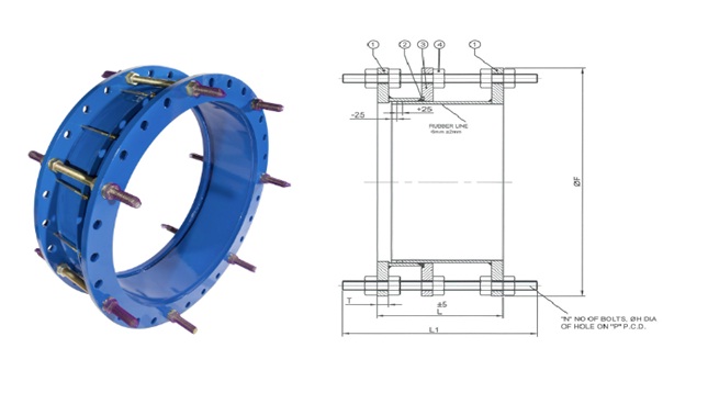
DISMANTLING JOINT
Gusto’s dismantling joints are designed to provide flexibility and easy access for maintenance and repairs in piping systems. These joints are ideal for connecting valves, pumps, and other equipment to pipelines where future removal and replacement are required.
PURPOSE
The primary purpose of a dismantling joint is to provide axial movement to a pipeline system, allowing for expansion and contraction due to temperature changes or settlement. The dismantling joint also allows for easy dismantling and removal of equipment for maintenance or replacement.
BENEFITS
One of the significant benefits of Gusto’s dismantling joints is that they allow for quick and easy installation, reducing labour costs and project timelines. Additionally, these joints are designed to withstand high pressures and temperatures, making them ideal for use in a wide range of applications. They also help to minimize stress on adjacent piping and equipment, reducing the risk of damage and extending the life of the pipeline system.
APPLICATIONS
Gusto’s dismantling joints are commonly used in a variety of industries, including water treatment, petrochemical, and power generation. They are ideal for connecting pumps, valves, and other equipment to pipelines, as well as for use in pipelines with high levels of vibration or where future maintenance is required.
The different parameters, as well as the size and material of the valve as per the tables, illustrations and details given in this page, to ensure that our valves match the requirements of your specific application.
CONTACT GUSTO’S EXPERTS TODAY TO HELP YOU CHOOSE THE RIGHT VALVE !
| Sl. No. | Description | Specification |
|---|---|---|
| 1 | Flange | WCB / A105N / A36 / IS 2062 |
| 2 | Seal Ring | EPDM / NBR |
| 3 | Follower | WCB / A105N / A36 / IS 2062 |
| 4 | Stud / Nut | A193 Gr B7 / A194 Gr 2H |
| TEST PRESSURE BAR |
|---|
| HYDROSTATIC (AWWA C219) |
| BODY |
| 20 |
| SIZE (mm) | L | L1 | ØF | ØR (RAISED FACE) | T | N | STUD | ØH | P |
|---|---|---|---|---|---|---|---|---|---|
| 100 NB | 200 | 310 | 229 | 157 | 17 | 8 | 5/8” x 11 UNC | 19 | 190.5 |
| 150 NB | 200 | 320 | 279 | 216 | 17 | 8 | 3/4” x 10 UNC | 22.2 | 241 |
| 200 NB | 220 | 350 | 343 | 270 | 22 | 8 | 3/4” x 10 UNC | 22.2 | 298.5 |
| 250 NB | 230 | 370 | 406 | 324 | 22 | 12 | 7/8” x 9 UNC | 25.4 | 362 |
| 300 NB | 250 | 410 | 483 | 381 | 22 | 12 | 7/8” x 9 UNC | 25.4 | 432 |
| 400 NB | 270 | 430 | 597 | 470 | 28 | 16 | 1” x 8 UNC | 28.5 | 540 |
| 500 NB | 280 | 460 | 699 | 584 | 28 | 20 | 1-1/8” x 8 UN | 31.7 | 635 |
| 600 NB | 300 | 500 | 813 | 692 | 32 | 20 | 1-1/4” x 8 UN | 35 | 749 |
| 700 NB | 300 | 550 | 927 | 800 | 32 | 28 | 1-1/4” x 8 UN | 34.9 | 864 |
| 800 NB | 320 | 600 | 1060 | 914 | 37 | 28 | 1-1/2” x 8 UN | 41.3 | 978 |
| 900 NB | 340 | 620 | 1168 | 1022 | 37 | 32 | 1-1/2” x 8 UN | 41.3 | 1086 |
| 1000 NB | 340 | 640 | 1289 | 1124 | 37 | 36 | 1-1/2” x 8 UN | 41.3 | 1200 |
| 1200 NB | 360 | 690 | 1511 | 1359 | 47 | 44 | 1-1/2” x 8 UN | 41.3 | 1422 |
| 1400 NB | 380 | 760 | 1746 | 1575 | 47 | 48 | 1-3/4” x 8 UN | 47.6 | 1651 |
| 1500 NB | 410 | 800 | 1854 | 1676 | 47 | 52 | 1-3/4” x 8 UN | 47.6 | 1759 |
TECHNICAL DATA
Class : PN10/PN16/150
Size : DN100 to DN1500
Material : WCB/A105N/A36/CF3/CF3M
Seal : EPDM/NBR
Flange : ISO1092-1